America’s insatiable appetite for electricity – turbocharged by the massive power requirements of hyperscale AI data centers – is driving utilities and commercial energy producers to increase grid capacity and build new power plants.
But many of the prime locations for large solar farms are already occupied, too expensive, or not in proximity to customers.
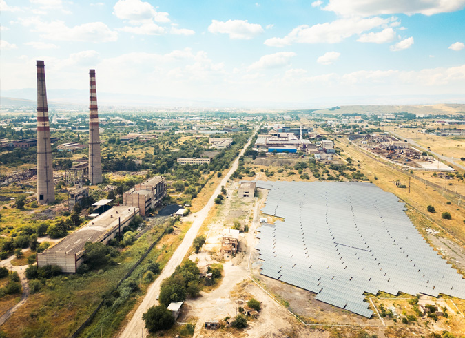
Consequently, utility-scale solar arrays and battery energy storage systems (BESS) are being constructed on lands deemed unsuitable for agricultural, residential or commercial use but remain well suited to energy projects.
Places include depleted farms and grazing lands, abandoned shopping malls, airports and manufacturing facilities, capped landfills, decommissioned strip mines and even former Superfund sites.
These are all examples of brownfields, and they all share one common trait: trenching is impossible or prohibited.
- Impossible when the land is a previous commercial site covered by asphalt or concrete (parking lots, runways, etc.) and/or has unmarked legacy water, sewage, power and communication lines underground. Some landfills are covered with an impenetrable membrane that prevents digging.
- Prohibited when the site is repurposed farmland, a mine, landfill or Superfund site and disturbing the ground could expose workers and nearby residents to toxic chemicals, gasses and pollutants and potentially contaminate local water supplies.
Creating Value from Unusable Land
Let’s consider an extreme case: Transforming a decommissioned strip mine into a solar array.
When work is halted at a strip mine, the owners are obligated to perform remediation and cover the scars from resource excavation with a fresh surface layer of earth. However, the instability of the loose ground impedes trenching and cannot support driven piles or buried foundations on which to mount heavy structures.
A rare example to be sure, but similar restrictions apply to all kinds of brownfield sites where the land is otherwise useless and trenching or ground penetration is not an option.
Snake Tray has the Solutions to Build on Brownfields
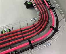 For these types of projects, flexible cabling solutions that do not involve digging or driven piles are required. Snake Tray provides two choices:
801 Series Solar Mega Snake (top). High capacity steel basket tray with prefabricated turns, T’s and crosses for fast, simple installation.
653 Series Aluminum Ladder (middle). Lightweight, ventilated ladder tray sections handle larger, heavier cable loads.
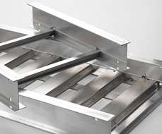 Highly conducive to brownfields and extreme environmental conditions, both the 801 and 650 series products are available in multiple widths and depths to easily handle varying cable sizes and loads. Both are compatible with a wide variety of mounting options, offer accessories such as turns, dropouts and covers, and are available in several finishes for climate-specific applications.
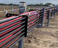 And for those instances when ground penetration is permitted on a brownfield site, Solar Snake Max™ (bottom) is the answer. Snake Tray’s patented free-air cable conveyance system eliminates the mess, labor, equipment and unforeseen obstacles of trenching by using driven piles and hard rails or messenger wire to maximize conductor capacity and energy throughput without digging.
Every brownfield is different, and Snake Tray has solutions for virtually every scenario. We encourage you to pick our brains to help you arrive at the best answer for your next project. Our advice and expertise is FREE!
Brownfield Solar: Take out the TRASH with Snake Tray
Let’s examine some key design parameters influenced by the limitations of building solar arrays on brownfields and why above-ground cable conveyance is the best option. Consider these issues and questions during the project discovery phase using Snake Tray’s T.R.A.S.H. methodology as a guide.
Terrain and Substrate
Most landfills are dome-shaped with a thin flat crest and sloped sides to prevent water pooling. This angled topology must be reviewed to determine how the cable conveyance and solar panel arrays will map to changes in site contour.
- Does the conveyance need to turn vertically or horizontally? Should it run perpendicular or parallel to the slope? Every change in elevation and direction increases BOM and costs with extra parts to navigate turns.
- Is the landfill membrane impenetrable or is limited penetration allowed for helical piles under certain circumstances? If the site has a concrete or asphalt layer, can the mounts be bolted to the surface? If not, the PV arrays and cable conveyance will need to be attached to weighted surface support such as precast concrete ballasts or Gabion baskets (wire cages filled with rocks). ASCE guidance is available to inform engineers about ballast size, weight, position/spacing, and how to prevent ballast sliding and panel uplift in heavy winds.
Establishing these facts about terrain and substrate informs decisions about supporting the cable conveyance.
TIP: Align cable conveyance routes in straight lines to minimize turns and elevation changes whenever possible for a simpler, more economical installation.
Racking
It is critical to know the type of racking system that will be used to support the PV arrays. There are many manufacturers and connection styles to choose from, and this decision will impact project design and cost in terms of whether the racking will also support the companion cable conveyance or if supplemental support is needed.
- Can the racking support the cable conveyance?
- Yes; use what’s there. The first and best option is bolting cable conveyance hardware to the PV array support system already in place to leverage project infrastructure.
- Yes; use more of what’s there. If there is not enough racking or the cabling requires additional support between racks as designed, option two is to use more of the same components (piles, ballast blocks, etc.) sourced from the same vendor so contractors know exactly how to install and attach them.
- No; the racking is off limits. Cable conveyance must be supported independently if the manufacturer stipulates the racking system cannot be used for cable tray attachment. Various ballasted and unballasted options are available to create a parallel cable conveyance.
- How much clearance is there for a cable conveyance system beside, beneath, or between the racking/array elements?Knowing which type of racking system will be used helps define the “window” through which cables must run and determine the size of a tray that will navigate those spaces with sufficient clearance.
For example, if using a racking system where the arrays bolt directly to ballasts, there is no room under the panels to route the cables. A routing plan must be devised that runs around the edge of the array rather than underneath it.
TIP: Consider the clearance area required under the array before making any decisions on cable conveyance.
Array Plan and Access Pathway
Review the proposed layout of the PV arrays with respect to access pathways, roads and rights-of-way that need to be kept clear for efficient operations, maintenance and vegetation management. Plan for how the cable tray will traverse these areas without impeding access or creating challenges for vehicles, equipment and people performing maintenance tasks. Road and access pathway crossings should be minimized wherever possible. When required, Snake Tray can recommend an appropriate road crossing solution.
For example, routing cable pathways through the center spaces between rows of PV panels may optimize the cable pathway but can make maintenance and mowing more difficult. There are trade-offs. Consider alternate methods to control vegetation growth such as gravel pads or chemical eradication.
Another consideration: As mentioned earlier, minimizing horizonal directional changes (turns) and designing PV rows in straight lines rather than arcs reduces BOM and costs.
- Are there any designated areas, roads or egresses on the site that cannot be touched?
- What type of vegetation is natural to the site that will regrow post-construction?
Understanding these variables and O&M strategies will help design more efficient tray routes.
TIP: On grassy fields, make sure cable trays are mounted at a height with sufficient clearance to allow lawn mowers to safely pass underneath.
System Topology
Beyond physical layout issues (straight rows or curved arcs, flat or sloped surfaces), system topology refers to how the DC electricity generated by the PV arrays are inverted to AC power that the grid can use. In other words, the order and placement of inverters, combiners, transformers and disconnects affects how these components interact with each other and determines where thinner string cables must be combined into larger conductors. This in turn impacts tray sizing and capacity of the cable conveyance at different points across the site.
- Are the inverters distributed around the array, with AC being brought back to a point of interconnection?
- Does the array feature DC combiners or load break disconnects (LBDs) throughout the array that combine strings into larger conductors that travel back to a centralized inverter rack?
- Are AC and DC conductors running on the same path? How many phases?
These must be separated as per NEC standards, which also affects conductor schedule.
System topology is also affected by ancillary circuits and cables that manage comms/data, auxiliary power, SCADA systems, and power the motors that allow the solar panels to track the sun.
Conductor length and voltage drop must also be considered. This is where free-air cable conveyance adds tremendous value by allowing for the use of lower ampacity conductors while boosting energy output.
TIP: Provide Snake Tray engineers with a schematic design, single-line diagram, conductor schedule, and plan view with circuit routing so we can help specify the right types and sizes of conveyances across the entire project.
Harsh Environment
Where is the site? To what hazards might the PV arrays and cables be exposed? The answers to these questions help determine the type of materials and weatherproofing that may be required to ensure conveyance components last for the life of the project.
- Are there corrosion concerns at the site due to landfill off-gassing (methane vents) or proximity to salty coastal air?
Choose the proper material given the environment, keeping in mind that the higher protection rating the material offers, the more expensive it will be. Galvanized steel is the least expensive option, powder-coated galvanized steel and aluminum add slightly to costs, while stainless steel is more costly but provides the most resistance to corrosion and failure in harsh environments. - Is pest mitigation a concern? What types…insects, rodents, deer?
Fully enclosed trays may be recommended to keep insects and termites away from cables. Ventilated tray covers can be used to prevent animals from chewing on cables while maintaining air flow. Different grid spacing options are available depending upon the typical size of pests native to the area. - What approach to vegetation management is being employed?
Overspray of exfoliant chemicals can damage conveyance materials. Ensure the right kind of protection/finish is applied to the tray.
Communicating these parameters to the cable tray provider will help determine the proper type of exposure protection and/or pest mitigation to be applied.
TIP: Seek guidance from the engineer of record and the regulatory Authority Having Jurisdiction (AHJ) over the site to determine the minimum level of material corrosion resistance required for the project.
Transform Useless Land into Energy Producing Assets with Snake Tray
Brownfields represent fertile ground for utility-grade solar plants – it’s one of the few uses left for otherwise useless land.
In this article we’ve offered a few site considerations and questions to get you started thinking about the process. Reach out to us to dig deeper (metaphorically speaking) and learn how Snake Tray makes it easy to transform useless brownfields into profitable energy producing assets.
We are Snake Tray. We are cable management.