Summary
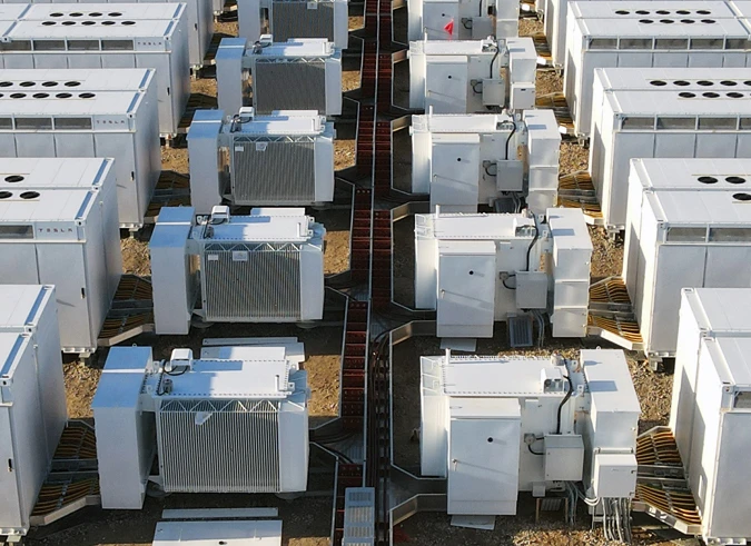
This article is intended to educate engineers, electrical contractors, utility companies and independent power producers on what a BESS is, how it stores and releases power and why utilities and facilities use them. It focuses on a critical element of BESS design: cable conveyance and best practices for planning cable pathways that maximize energy storage and distribution efficiency.
Learn which major components and cable circuits make up a BESS, how buried and free-air BESS cable conveyance methods compare, the impact of civil, structural, electrical and maintenance factors on cable routing, and why enlisting the early involvement of cabling expertise from Snake Tray is central to BESS project success.
For a deeper dive on any of the topics covered here, click on the links provided to read the full article or visit the Snake Tray BESS product page.
Related Product:
Why Battery Energy Storage Matters
As electricity demand fluctuates and renewable generation continues to grow, the ability to store surplus energy and deliver it when needed has become increasingly important.
A battery energy storage system (BESS) stores excess electricity in large battery arrays during periods of lower demand or high renewable generation. It releases power to the grid or a connected facility later when demand rises, solar production declines, or during an outage.
Utility-scale BESS installations are commonly paired with solar arrays, while privately owned businesses such as data centers, hospitals, manufacturing facilities and critical infrastructure services that require “always-on” power often build their own BESS for emergency purposes.
A BESS is more than a collection of batteries. It also includes the infrastructure and cable conveyance that move electrons safely between components. Understanding how power flows through these interconnected systems – and how the cables that connect them are routed and secured – is essential for planning reliable energy storage projects.
What Is a BESS and How Does It Work?
A battery energy storage system is an integrated collection of equipment designed to store electrical energy and release it when power is required. Although batteries are the most visible part of the installation, they are only one element of a larger system. Inverters, transformers, protection equipment, voltage controls and cabling support infrastructure all work together to charge, store, convert and deliver electricity on demand.
The operating sequence is relatively straightforward.
When excess electricity is available, often from a solar array or another renewable source, it is directed into the battery array. The batteries store this energy as direct current (DC). Rather than being used immediately, the electricity remains stockpiled until the connected utility or facility requires additional power.
When demand increases, the stored DC electricity is released from the battery array to the inverter, which converts the stored DC power into alternating current (AC) compatible with the electrical grid and most commercial electrical systems. After conversion, transformers step down the voltage as needed before electricity is delivered either to the utility grid or directly into the connected facility.
It is also helpful to distinguish between power and energy when discussing BESS system size. A system rated in megawatts (MW) describes how much power it can deliver at one time. Megawatt-hours (MWh) describe how much energy is stored and therefore how long the system can sustain its output before requiring recharging.
Throughout both charging and discharging processes, the same high-current cable pathways carry electricity between the battery arrays and the inverters. The direction of power flow changes depending on whether the batteries are charging or supplying energy, but the cable infrastructure supports both operating modes. This makes cable routing, support, accessibility, and protection important considerations from the earliest stages of BESS project planning.
Why Utilities and Facilities Use BESS
Battery energy storage systems provide flexibility by allowing electricity generated at one time to be used later when demand is higher, or generation is lower.
A BESS can be a profit center for utilities by storing excess power produced cheaply during the day and discharging it to the grid when rates are higher. Energy producers boost output, increase margins and reduce their carbon footprint by reselling low cost stored electricity without firing up natural gas or fossil fuel-powered turbines.
Beyond daily operations, battery storage can also improve utility resilience. During equipment failures, rolling blackouts, wildfires, severe weather events or peak period spikes, stored electricity helps maintain service and supplement supplies while normal power sources are restored.
Private entities connected to a BESS can tap into cheap power on demand to lower grid dependence and gain electrical redundancy to insulate operations from outages. Examples include data centers that require continuous cooling to support digital infrastructure, hospitals that depend on uninterrupted power for surgical suites and life-saving equipment, businesses handling refrigerated or perishable goods, and manufacturing facilities and service providers that need constant current for 24/7 operations.
Battery storage can contribute to operational efficiency and improved system flexibility; however, project economics depend on numerous technical and operational variables. The capacity (megawatts, or power) and duration of operation (megawatt hours, or stored energy) depend on system size and project design. Indeed, the selected cabling method can also impact BESS performance. Therefore, any aspect of financial ROI should be evaluated separately from the benefits of using a BESS to maintain operational continuity.
Main BESS Components and Cable Path
Understanding the flow of a battery energy storage system is easiest when following the path electricity takes through the installation.
|
Component |
Primary Function |
|
Energy Source (solar/wind/water/nuclear/fossil fuel) |
Generate power |
|
Battery containers or arrays |
Receive and store DC electricity during charging and supply stored DC power during discharge |
|
Inverters |
Convert stored DC electricity into usable AC power for the connected grid or facility |
|
Transformers |
Adjust voltage to match grid or facility requirements before power is delivered |
The common denominator across all components is the cable plant; the conductors that connect the energy source, battery arrays, inverters, transformers and supporting systems to each other and the grid or facility.
While electricity follows this primary route, different circuit types operate within the BESS:
- High-voltage DC circuits connect battery arrays to power conversion equipment.
- Medium-voltage power circuits distribute converted electricity to transformers and the grid or facility connection.
- String cables carry electrons from each energy source (usually solar panels) to combiner points.
- Additional low-voltage circuits support performance monitoring and communications, auxiliary systems and fire-suppression equipment.
Because these circuits overlap and occupy the same project site, cable routing requires careful planning. Engineers must consider how cables will be separated to reduce congestion, maintain appropriate clearances, offer access and support safe operation.
Factors such as the size, shape and number of batteries in the array, the presence of access roads, natural boundaries and water tables, plus the physical location of connection terminals impact conductor schedule, cable bend radius, spacing and maintenance decisions.
Rather than treating cable infrastructure as an afterthought, most projects benefit from coordinating cable pathways with equipment layout.
Then there is the issue of performance and how to move electricity between sources, batteries and the grid with the greatest level of efficiency and minimal energy loss. This leads to a critical decision: whether to trench and bury cables or run them above ground.
BESS Cabling Options: Buried or Free-Air
The method used to route cables in a battery energy storage installation has significant implications for construction, maintenance and future expansion. Two common approaches are buried cable conveyance and Snake Tray’s patented free-air cable conveyance system. Each has unique advantages depending on project requirements and site conditions.
Buried Cable Conveyance
Burying cables underground is a time- and labor-intensive process of excavating trenches stretching from the energy source to the battery array. After digging, cables are laid, possibly alongside protective materials or separators. The trenches are then backfilled, and cable routes are marked for future identification.
Ground conditions can significantly influence installation complexity. Soil type, rock formations, groundwater, weather, existing underground utilities, tree roots, environmental restrictions and limited access may all increase construction efforts or affect project schedules. Heavy equipment is required for excavation, and some locations impose restrictions on future digging activities after installation (like landfills).
Buried cables trap heat, so they must be “derated” or stepped up in ampacity to compensate for the insulative effects and energy loss when cables are trenched or bundled. This can increase conductive material costs by 25% to 40%.
Once buried, cable routes become less visible. While route markers help identify approximate locations, things can move over time. Locating faults, replacing damaged cables or adding new circuits requires additional excavation.
Despite these considerations, underground cabling may still be required or preferred because of site constraints, owner preferences, permitting requirements or other project-specific factors.
Free-Air Cable Conveyance
Above ground cable conveyance – invented by Snake Tray – supports PV cables in free air using separators attached to hard rails and mounted to driven piles or tensioned wire systems.
Although above-ground conveyance requires more engineering coordination with structural supports, grounding, precise cable spacing and protection from environmental elements, it solves most problems associated with trenching:
- There’s no digging or heavy earth moving equipment needed; just support piles hammered into the ground.
- Separating cables in free air promotes natural air circulation around conductors, which assists with heat dissipation and improves energy efficiency.
- Traverses any type of terrain and distance yet remains immune to changing geological and soil conditions.
- Cables are loaded faster with total visibility to the cable plant for simplified inspection, maintenance, repairs and future expansion.
- Most importantly, above ground cable conveyance maximizes ROI by eliminating the need to derate cables, simultaneously reducing conductive material costs while harvesting up to 8% more metered energy than buried cables by eliminating the loss of electrons to heat conversion.
Design Considerations for BESS Cabling
No two BESS projects are ever alike, but they all are influenced by similar external and environmental factors. Consider these four design categories during project development before committing resources and budget to cabling:
1. Civil and Site Planning
Site planning establishes the physical framework and layout for the entire installation. Access roads, drainage, natural boundaries, water tables, topography, soil conditions, available space and environmental constraints all influence equipment placement and should be surveyed.
Longer distances between energy sources and battery arrays affect cable lengths and therefore impact conductor costs. Buried cables must be spaced sufficiently apart to allow for heat dissipation, further increasing overall footprint. Tighter spacing/greater density is achieved with above-ground cable conveyance and in turn can reduce conductive material costs.
Planning these pathways early helps coordinate equipment placement before construction begins and can reduce the need for costly on-site fabrication.
2. Structural and Equipment Interfaces
Batteries, inverters and transformers usually arrive pre-assembled with fixed cable attachment locations. Oftentimes cable interconnection points are positioned on the underside of equipment, requiring elevation and support structures.
Cable support systems must accommodate these changes in direction and elevation. They must also adhere to bend radius requirements for various diameter cables while maintaining organized routing and separation.
Identifying interface locations before pathways are finalized can simplify installation and reduce field modifications during construction.
3. Electrical Performance and Protection
Electrical performance depends on more than conductor selection alone. Designers must also consider cable separation and heat dissipation when trenching, and ground clearance, conductor routing, protective covers and the ability of support systems to withstand expected loading conditions in above ground systems.
Fault forces, environmental exposure, and cable protection strategies should be addressed as part of the overall engineering process. Buried cables are susceptible to damage from exposure to constant heat, pressure, geologic events, frost heave, tree roots, moisture and subterranean insects. Free-air conveyance must maintain adequate cable clearance above the ground and ensure continuous 360° air flow around each cable as per NEC Table 310.17.
Maintaining organized cable pathways can also simplify identification and reduce congestion where multiple circuit types share common routing corridors.
4. Operations and Maintenance
Maintainability should be incorporated into the initial design rather than addressed after construction.
Visible above ground cable routes simplify inspections, assist with identifying damaged components, and improve access when replacement or modifications become necessary. However, trenching makes ground maintenance easier whereas free-air systems can present obstacles for vehicles and lawn mowers. Assessing the types of vegetation that will grow on site and associated pest control measures will point you to the best option.
Future expansion should also be considered during initial layout planning. Adding more batteries, inverters and transformers may require new cable routes. Designing with expansion in mind can reduce disruption if capacity is added later.
Related Article:
Design Considerations When Cabling Battery Energy Storage Systems (BESS)
Snake Max Cable Management for BESS
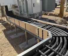
If your next BESS project is a candidate for above-ground cable conveyance, there’s really only one choice: Snake Tray’s patented Snake Max® for Battery Energy Storage Systems.
Snake Max for BESS is Snake Tray’s above-ground solar cable conveyance solution adapted for battery energy storage applications. The system uses molded cable separators called “clicks” mounted to galvanized steel or aluminum side rails to create organized pathways for cables up to 1250 Kcmil. Repeatable components accommodate straight runs, directional changes, elevation transitions and on-the-fly routing adjustments across the project site.
Snake Max for BESS is the only solution that provides consistent support while maintaining end-to-end cable separation equal to at least one cable diameter as mandated by NEC Table 310.17, allowing for natural heat dissipation into the surrounding air to maximize energy throughput.
Remember, the same cables that feed excess power into the batteries are also used to push power out to the grid. When that switch is flipped, a tremendous amount of heat is generated as current flows through the cables. This is where the benefit of free air installation comes to the fore, allowing for maximum energy transfer between battery and inverter, and harvesting up to 8% more power than can be collected from a trenched cable system.
Where cables remain exposed, covers can be incorporated for protection from vehicles and pests. Open sections allow for easy access to cable terminations or equipment connections.
Maintaining visibility to the cable plant allows installers to speed cable loading during construction and inspectors to quickly assess cable condition and pinpoint faults during routine maintenance. Optional side-car trays can be added for communications, data and fire-suppression systems, allowing different circuit types to remain organized while sharing common routing corridors. If a replacement is required, individual cables remain accessible without requiring excavation. For expansion, simply add another layer of “clicks.”
These features directly address many of the cable management considerations discussed throughout this article. Depending on project requirements, above-ground conveyance can reduce trenching, provide routing flexibility, improve natural air circulation around conductors, boost energy throughput, simplify maintenance and facilitate future capacity additions.
Moreover, above-ground conveyance may also be suitable for retrofit installations at existing solar facilities adding battery storage as well as new projects designed with integrated BESS infrastructure from the outset.
Related Article:
Making the Case for Solar Snake Max in Battery Energy Storage
Snake Tray’s Cable Management Solution for Battery Energy Storage Systems Makes Every Day Brighter
Snake Tray: Your Early-Stage Cable Management and Engineering Resource
BESS performance is influenced by many factors including conductor schedule, cable routing, equipment spacing, elevation/structural supports, bend radius and long-term maintenance. Bringing in Snake Tray expertise before breaking ground to evaluate project parameters with an eye on standards and compliance can help optimize BESS cabling design, speed project completion and reduce costs.
Our advice is free, but its value is priceless. Reach out to us at Snake Tray.com.
Frequently Asked Questions
What is a battery energy storage system?
A BESS is an integrated installation that stores electrical energy for later use. It includes battery arrays, battery management systems, inverters, transformers, control equipment, safety systems and supporting electrical infrastructure that work together to manage and deliver reliable power.
How does a BESS move power to and from the grid?
A BESS charges by drawing excess electricity from the grid or renewable energy sources and storing it as direct current (DC) within battery cells. During discharge, inverters convert the stored DC into alternating current (AC), supplying power safely and efficiently back to the grid.
Can BESS cables be installed above ground?
Yes. Where local regulations, project requirements and engineering standards allow, BESS cables may be installed using free-air conveyance systems. Proper design considers cable support, thermal performance, environmental exposure, maintenance access and long-term reliability to ensure safe operation.
When should BESS cable management be planned?
BESS cable management should be coordinated during the earliest stages of civil, structural, and electrical design. Early planning helps optimize routing, reduce conflicts, support future maintenance and minimize costly improvisations during construction and commissioning.